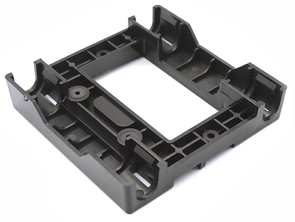
Injection Molding
At a Glance
Lifecycle
Lead Time
Materials
Finishing Options
Rapid design molds, ideal for validating part designs, low volume production, or bridge production quantities (1 - 10k units)
Production tooling, ideal for higher quantity part orders (10k - 500k units)
Production tooling, ideal for higher quantity part orders (10k - 500k units)
Starts at 14 business days
SPI A-D, mold-tech equivalent texture
About the Process
Injection molding is ideal for end-use parts manufactured at mid to high volumes (100 - 500,000+ units).
For rapid design molds, customers can receive T1 samples off a steel tool in as fast as 10 business days. Customers own the core and cavity inserts and we use factory-owned, interchangeable mold base inserts.
For production tooling, we produce stand-alone tools, ultimately owned by the customer. P20, H13, S7, NAK80, and SS420 insert steel is available as well as family & multi-cavity tools.
Shapefy also offers specialized processes including insert molding (substrate tool + overmold tool), overmolding (rigid + elastomer, dual barrel machines), and compression molding.
Our Capabilities
Name
Description
Single Cavity Molds
Molds containing only one cavity, producing one unit per run.
Molds with side-action cores
Cores slide out of the part from the side before it is ejected from the mold. This allows for undercuts to be molded.
Multi-cavity molds
Multiple identical cavities are machined into the mold tool. This allows for more parts to be produced per shot, minimizing the unit costs.
Family Molds
Several parts are designed into the same mold tool. This allows for the minimization of tooling costs.
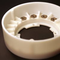
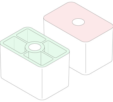
Insert molding
Inserts are placed into the mold and molding occurs around them. This allows for inserts such as helicoils to be molded in your design.
Overmolding
Premade parts are placed into the mold to mold over them. This allows for multi-material injection molding.
Additives and fibers
Shapefy offers additives and reinforcements as options for your plastics parts.Name
Description
UV absorbers
Absorb UV radiation, slowing down the degradation of the material when used outdoors.
Flame retardants
Prevent ignition and inhibits spread of fire.
Plasticizers
Increase flexibility and promotes plasticity, reducing brittleness of the material.
Colorants
Used to color plastics.
Carbon Fibers
Increase strength, toughness, and rigidity of the material at the expense of making the material more brittle.
Glass fibers
Increase strength, toughness, and rigidity of the material at the expense of making the material more brittle. It is more flexible than carbon fibers.
Surface Finish
Injection molded parts are not usually post-processed, but the mold itself can be finished to affect the surface finish of the molded part.This way aesthetic needs or technical requirements can be achieved.
Name
SPI Standard
Description
Application
Glossy
A-1, A-2, A-3
The mold is smoothed and then polished with a diamond buff, resulting in parts with a mirror-like finish.
Suitable for parts that need the smoothest surface finish for cosmetic or functional purposes (Ra < 0.10 μm)
Semi-gloss
B-1, B-2, B-3
The mold is smoothed with fine grit sandpaper, resulting in parts with a fine surface finish.
Suitable for parts that require a good visual appearance, but not a high glossy look.
Matte
C-1, C-2, C-3
The mold is smoothed using fine stone powder, removing all machining marks.
Suitable for parts with low aesthetic requirements, but when machining marks are not acceptable.
Textured finish
D-1, D-2, D-3
The mold is first smoothed with fine stone powder and then sandblasted, resulting in a textured surface.
Suitable for parts that require a satin or matte textured surface finish.
As-machined finish
The mold is finished to the machinist's discretion. Tool marks may be visible.
Suitable for non-cosmetic, industrial parts or hidden components.
Materials
We offer any commercially available injection molding material, including:Name
Description
ABS
Common thermoplastic with high impact resistance, low-cost & low density. Vulnerable to solvents.
Nylon (PA 6)
Engineering thermoplastic with excellent mechanical properties and high chemical & abrasion resistance. Susceptible to moisture.
PC/ABS
Blend of two thermoplastics resulting in high impact strength, excellent thermal stability, and high stiffness. Vulnerable to solvents.
Polyurethane (PU)
Thermoplastic with high impact strength and good mechanical properties & hardness. Suitable for molding parts with thick walls.
Acrylic (PMMA)
UV resistant plastic with good abrasion resistance, stiffness and hardness.
Polypropylene (PP)
The most common Injection molding plastic. Excellent chemical resistance. Food-safe grades available. Not suitable for mechanical applications.
Polyethylene (PE)
Lightweight thermoplastic with good impact strength & weather resistance. Suitable for outdoor applications.
High density polyethylene (HDPE)
Excellent strength-to-weight ratio, impact and weather resistant.
Polystyrene (PS)
The Injection molding plastic with the lowest cost. Food-safe grades available. Not suitable for mechanical applications.
Polycarbonate (PC)
The plastic with the highest impact strength. High thermal resistance, weather resistance & toughness. Can be colored or transparent.
Polyvinyl chloride (PVC)
Light weight plastic with good mechanical strength and abrasion resistance. Generally used in building and construction applications.
PEEK
High-performance engineering thermoplastic with excellent strength and thermal & chemical resistance. Used to replace metal parts.
POM (Acetal/Delrin)
Engineering thermoplastic with high strength, stiffness & moisture resistance and self-lubricating properties. Relatively prone to warping.
Design Recommendations
Wall thickness
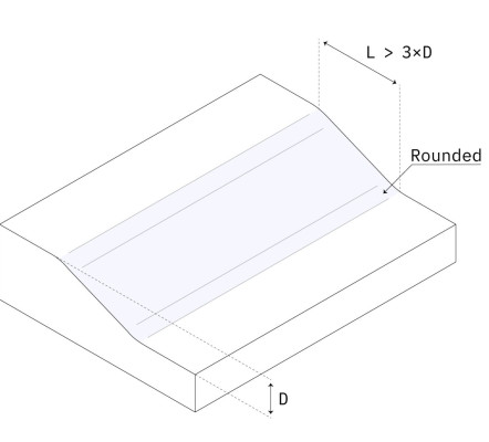
Smooth transitions
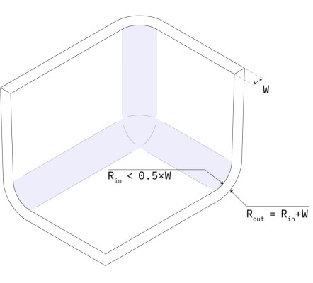
Rounded edges
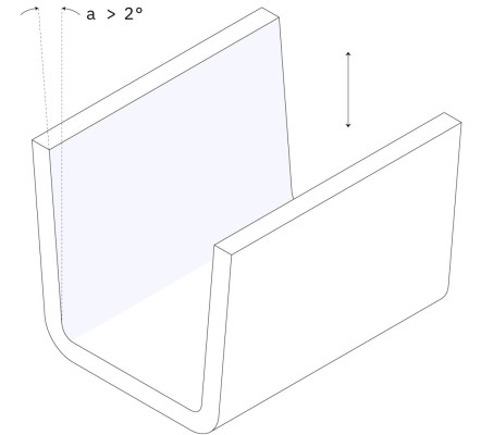
Draft Angle
Thickness: 1 mm and 3 mm
3 × wall thickness difference
Internal edges: > 0.5 × wall thickness. External edges: internal fillet + wall thickness
For parts taller than 50 mm: increase the draft by 1° for every 25 mm. For parts with a textured finish: increase the draft by an extra 1°-2°
Colors
- Pantone color matching
- RAL color matching
- Physical sample color matching
Post-Processing Services
- Hardware installation (e.g. heat stakes inserts, ultrasonically welded inserts)
- Pad printing
- Silk screening
- Painting
- Ultrasonic welding
- Light assembly
- Protective packaging/film